
The manufacture and design of Vacuum Insulated Piping System for liquid nitrogen conveying is the responsibility of the supplier. For this project, if the supplier does not have the conditions for on-site measurement, the pipeline direction drawings need to be provided by the house. Then the supplier will design VI Piping System for liquid nitrogen scenarios.
The supplier shall complete the overall design of the pipeline system by experienced designers according to the drawings, equipment parameters, site conditions, liquid nitrogen characteristics and other factors provided by the demander.
The content of the design includes the type of system accessories, the determination of the material and specifications of the internal and external pipes, the design of the insulation scheme, the prefabricated section scheme, the connection form between the pipe sections, the internal pipe bracket, the number and position of the vacuum valve, the elimination of gas seal, the cryogenic liquid requirements of the terminal equipment, etc. This scheme should be verified by the professional personnel of the demander before manufacturing.
The content of Vacuum Insulated Piping System design is broad, here to HASS applications and MBE equipment in some common problems, a simple chat.
VI Piping
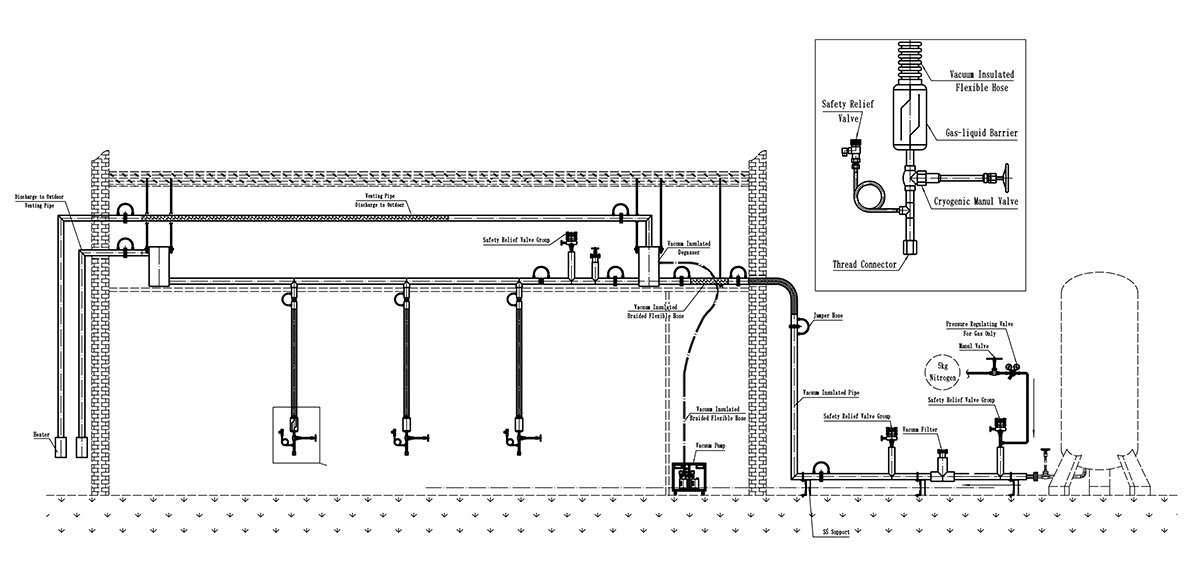
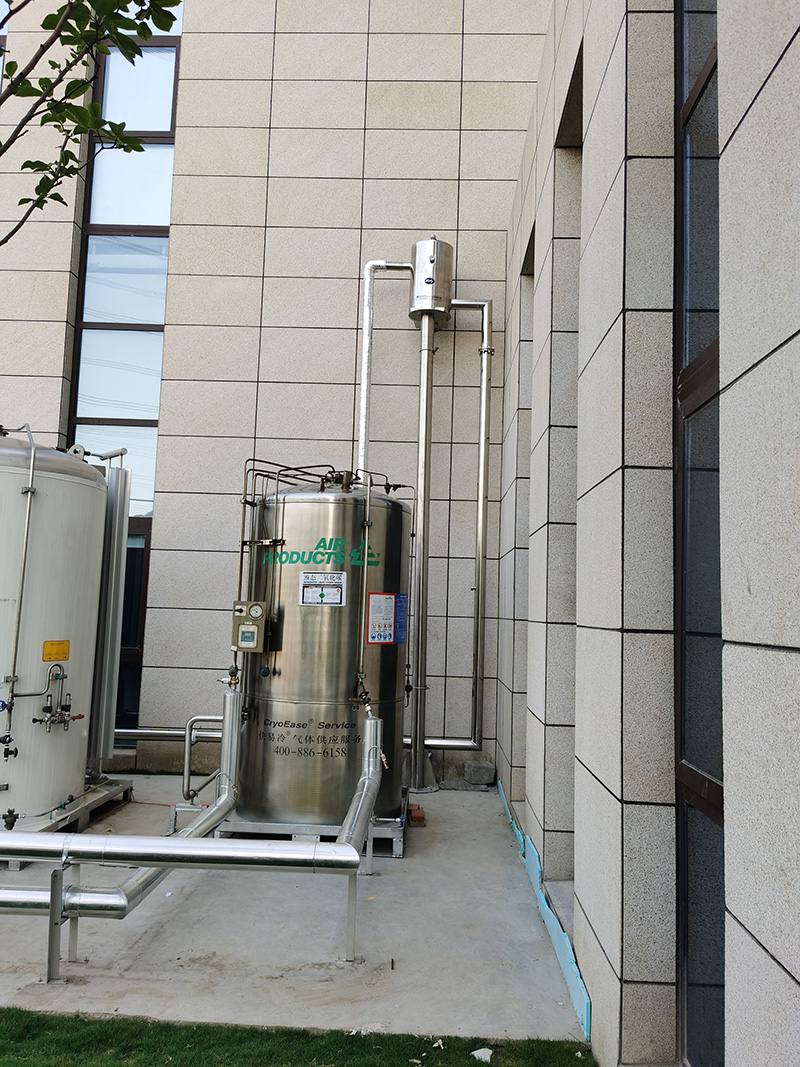
The liquid nitrogen storage tank is usually long from HASS Application or MBE equipment. While the vacuum insulated pipe enters the building indoor, it needs to be reasonably avoided according to the room layout in the building and the location of the field pipe and air duct. Therefore, transporting liquid nitrogen to the equipment, at least hundreds of meters of pipe.
Because the compressed liquid nitrogen itself contains a large amount of gas, coupled with the distance of transportation, even the vacuum adiabatic pipe will produce a large amount of nitrogen in the transportation process. If nitrogen is not discharged or the emission is too low to meet the requirements, it will cause gas resistance and lead to poor flow of liquid nitrogen, resulting in a great reduction in the flow rate.
If the flow rate is insufficient, the temperature in the liquid nitrogen chamber of the equipment cannot be controlled, which may eventually lead to the damage of the equipment or product quality.
Therefore, it is necessary to calculate the amount of liquid nitrogen used by the terminal equipment (HASS Application or MBE equipment). At the same time, pipeline specifications are determined according to pipeline length and direction, as well.
Starting from liquid nitrogen storage tank, if the main pipeline of the vacuum insulated pipe/hose is DN50 (inner diameter φ50 mm), its branch VI pipe/hose is DN25 (inner diameter φ25 mm), and the hose between the branch pipe and the terminal equipment is DN15 (inner diameter φ15 mm). Other fittings for VI piping system, including Phase Separator, Degasser, Automatic Gas Vent, VI/Cryogenic (Pneumatic) Shut-off Valve, VI Pneumatic Flow Regulating Valve, VI/Cryogenic Check Valve, VI filter, Safety Relief Valve, Purge system, and Vacuum Pump etc.
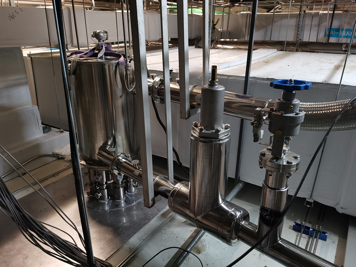
MBE Special Phase Separator
Each MBE special normal pressure phase separator has the following functions:
1. Liquid level sensor and automatic liquid level control system, and promptly displayed through an electrical control box.
2. Pressure reduction function: the liquid inlet of the separator is equipped with a separator auxiliary system, which guarantees a liquid nitrogen pressure of 3-4 bar in the main pipe. When entering the Phase Separator, steadily reduce the pressure to ≤ 1Bar.
3.Liquid inlet flow regulation: a buoyancy control system is arranged inside the Phase Separator. Its function is to automatically adjust the amount of liquid intake when the liquid nitrogen consumption increases or decreases. This has the advantage of reducing the sharp fluctuation of pressure caused by the entry of a large amount of liquid nitrogen when the inlet pneumatic valve is opened and preventing overpressure.
4. Buffer function, the effective volume inside the separator guarantees the maximum instantaneous flow of the device.
5. Purge system: airflow and water vapor in the separator before the liquid nitrogen passage, and discharge of liquid nitrogen in the separator after the liquid nitrogen passage.
6. Overpressure automatic relief function: The equipment, when initially passing through liquid nitrogen or under special circumstances, leads to an increase in liquid nitrogen gasification, which leads to instantaneous overpressure of the entire system. Our Phase Separator is equipped with Safety Relief Valve and Safety Relief Valve Group, which can more effectively ensure the stability of pressure in the separator and prevent the MBE equipment from being damaged by excessive pressure.
7. Electrical control box, real-time display of liquid level and pressure value, can set the liquid level in the separator and liquid nitrogen into the amount of control relationship. At the same time. In emergency, manual braking of the gas liquid separator into the liquid control valve, for the site personnel and equipment safety to provide a guarantee.
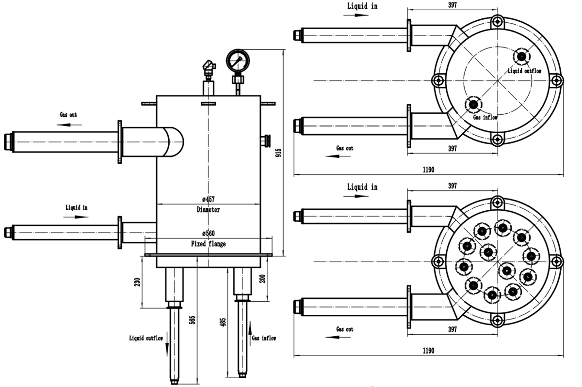
Multi-core Degasser for HASS Applications
The outdoor liquid nitrogen storage tank contains a large amount of nitrogen because it is stored and transported under pressure. In this system, the pipeline transportation distance is longer, there are more elbows and greater resistance, which will cause partial gasification of liquid nitrogen. Vacuum insulated tube is the best way to transport liquid nitrogen at present, but heat leakage is unavoidable, which will also lead to partial gasification of liquid nitrogen. To sum up, liquid nitrogen contains a large amount of nitrogen, which leads to the generation of gas resistance, resulting in the flow of liquid nitrogen is not smooth.
Exhaust equipment on vacuum insulated pipe, if there is no exhaust device or insufficient exhaust volume, will lead to gas resistance. Once the gas resistance is formed, the liquid nitrogen conveying capacity will be greatly reduced.
The Multi-core Degasser designed exclusively by our company can ensure the nitrogen discharged from the main liquid nitrogen pipe to the maximum extent and prevent the formation of gas resistance. And the Multi-core Degasser has enough internal volume, can play the role of buffer storage tank, can effectively meet the needs of the maximum instantaneous flow of solution pipeline.
Unique patented multi-core structure, more efficient exhaust capacity than our other types of separators.
Continuing with the previous article, there are some issues that need to be considered when designing solutions for Vacuum Insulated Piping System for cryogenic applications in the Chip Industry.
Two Types of Vacuum Insulated Piping System
There are two types of Vacuum Insulated Piping System: Static VI System and Dynamic Vacuum Pumping System.
Static VI System means that after each pipe is made in the factory, it is vacuumed to the specified vacuum degree on the pumping unit and sealed. In the field installation and put into use, a certain period of time do not need to be re-evacuated to the site.
The advantage of Static VI System is low maintenance costs. Once the piping system is in service, maintenance is required several years later. This vacuum system is suitable for systems that do not require high cooling requirements and open places for onsite maintenance.
The disadvantage of Static VI System is that vacuum decreases with time. Because all materials release trace gases all the time, which is determined by the physical properties of the material. The material in the jacket of VI Pipe can reduce the amount of gas released by the process, but cannot be completely isolated. This will lead to the vacuum of the sealed vacuum environment, will be lower and lower, vacuum insulation tube will gradually weaken the cooling ability.
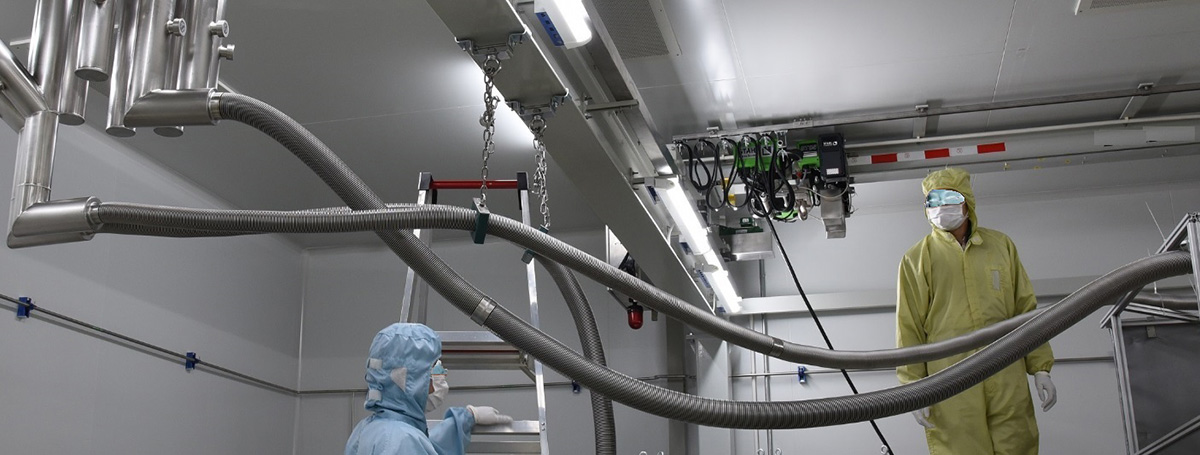
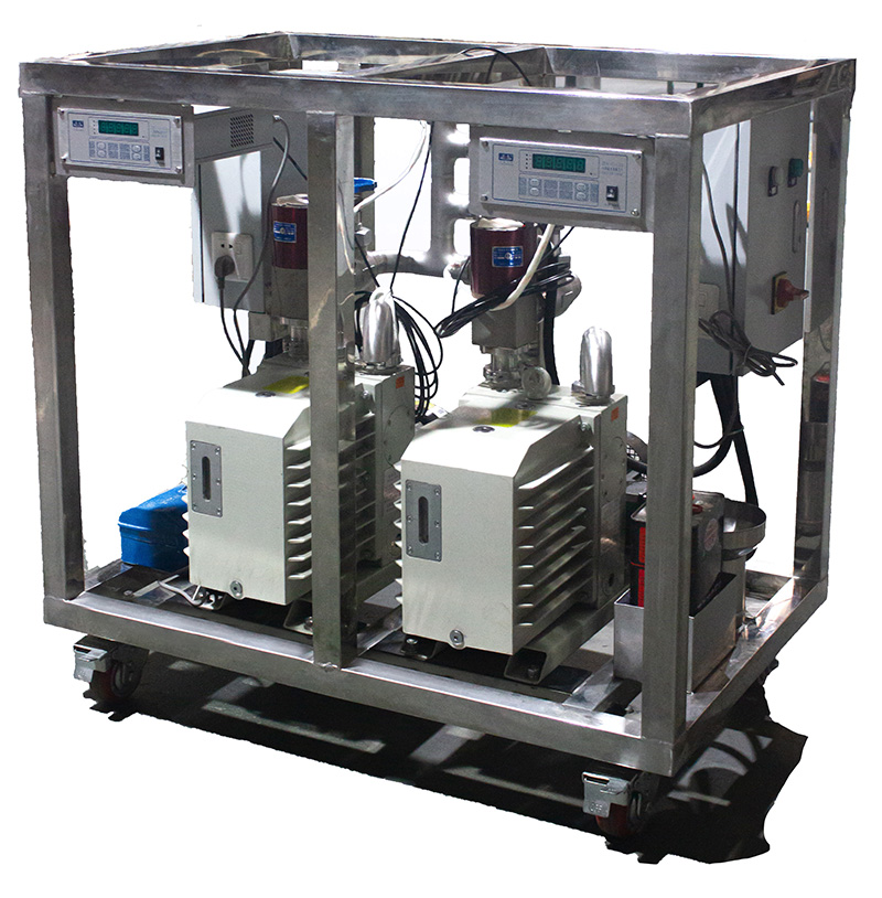
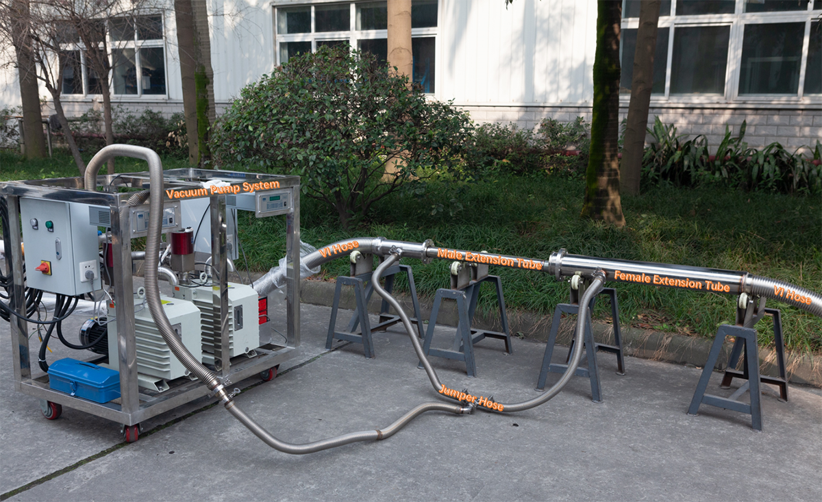
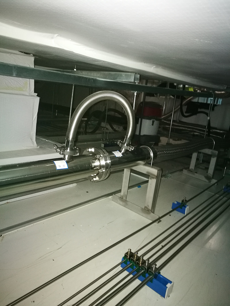
Dynamic Vacuum Pumping System means that after the pipe is made and formed, the pipe is still evacuated in the factory according to the process of leak detection, but the vacuum is not sealed before delivery. After the field installation is completed, the vacuum interlayers of all pipes shall be connected into one or more units by stainless steel hoses, and a small dedicated vacuum pump shall be used to vacuum the pipes in the field. Special vacuum pump has an automatic system to monitor the vacuum at any time, and vacuum as needed. The system runs 24 hours a day.
The disadvantage of Dynamic Vacuum Pumping System is that the vacuum needs to be maintained by electricity.
The advantage of Dynamic Vacuum Pumping System is that the vacuum degree is very stable. It is preferentially used in the indoor environment and vacuum performance requirements of very high projects.
Our Dynamic Vacuum Pumping System, the whole mobile integrated special vacuum pump to ensure the equipment to vacuum, convenient and reasonable layout to ensure the effect of the vacuum, quality of the vacuum accessories to ensure the quality of the vacuum.
For the MBE project, because the equipment is in the clean room, and the equipment is running for a long time. Most of the vacuum insulated piping system is in the closed space on the interlayer of the clean room. It is impossible to implement the vacuum maintenance of the piping system in the future. This will have a serious impact on the long-term operation of the system. As a result, the MBE project employs almost all Dynamic Vacuum Pumping System.
Pressure Relief System
The pressure relief system of main line adopts Safety Relief Valve Group. Safety Relief Valve Group is used as a Safety protection system when overpressure, VI Piping cannot be adjusted in normal use
Safety Relief Valve is a key component to ensure that the pipeline system will not be overpressure, safe operation, so it is essential in the pipeline operation. But the safety valve according to the regulation, must be sent to check every year. When one safety valve is used and the other is prepared, when one safety valve is removed, the other safety valve is still in the pipeline system to ensure the normal operation of the pipeline.
The Safety Relief Valve Group contains two DN15 Safety Relief Valves, one for use and one for standby. In normal operation, only one Safety Relief Valves is connected with the VI Piping System and runs normally. The other Safety Relief Valves is disconnected from the inner pipe and can be replaced at any time. The two safety valves are connected and cut off through the side valve switching state.
The Safety Relief Valve Group is equipped with a pressure gauge to check the piping system pressure at any time.
The Safety Relief Valve Group is provided with a discharge valve. It can be used to discharge the air in the pipe when purging, and nitrogen can be discharged when the liquid nitrogen system is running.
HL Cryogenic Equipment
HL Cryogenic Equipment which was founded in 1992 is a brand affiliated to Chengdu Holy Cryogenic Equipment Company in China. HL Cryogenic Equipment is committed to the design and manufacture of the High Vacuum Insulated Cryogenic Piping System and related Support Equipment.
In today’s rapidly changing world, providing advanced technology while maximizing cost savings for customers is a challenging task. For 30 years, HL Cryogenic Equipment Company in almost all cryogenic equipment and industry have a deeper into application scene, has accumulated rich experience and reliable, and continuously explore and strive to keep up with the latest developments in all walks of life, providing customers with new, practical and efficient solutions, make our customers more competitive in the market.
For more information, please visit the official website www.hlcryo.com, or email to info@cdholy.com .

Post time: Aug-25-2021


