
The liquid nitrogen cooling systems are widely used in the semiconductor & chip industry, including the process of,
- The technology of Molecular Beam Epitaxy (MBE)
- The chip's test after COB package
Related Products
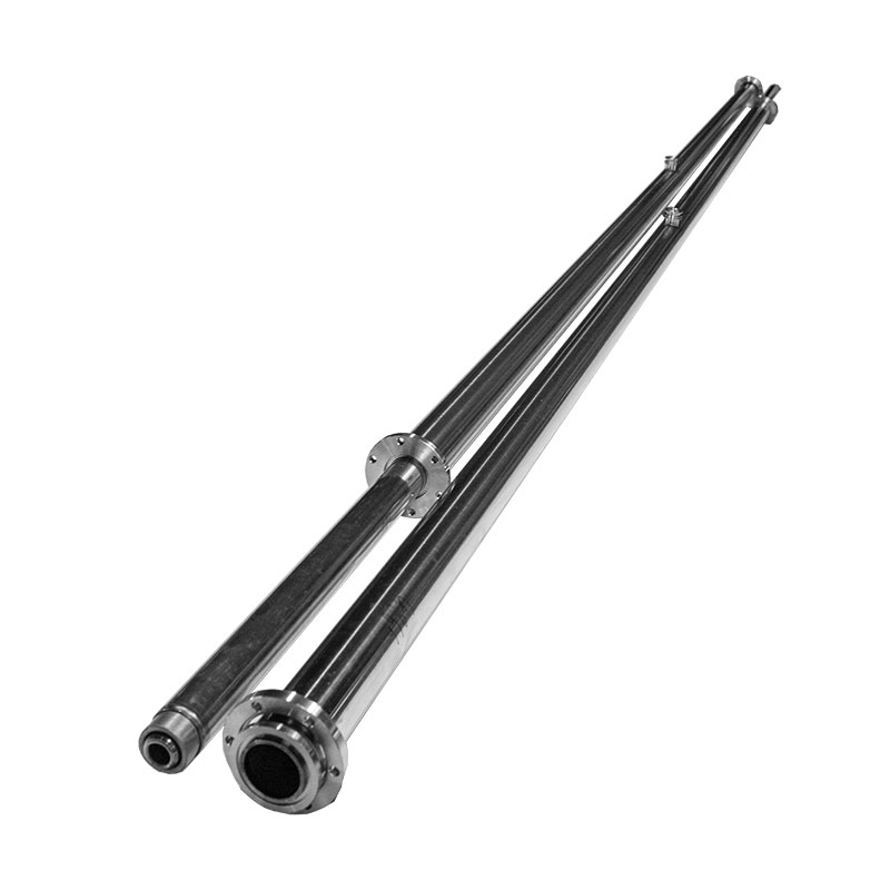
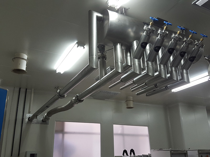
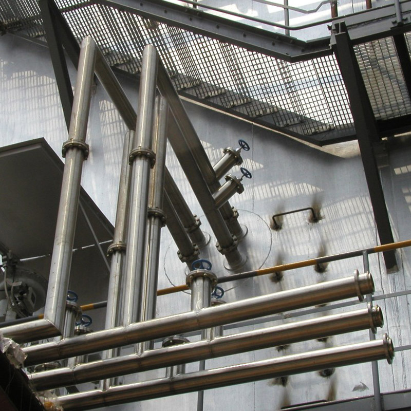
Vacuum Insulated Pipe Series
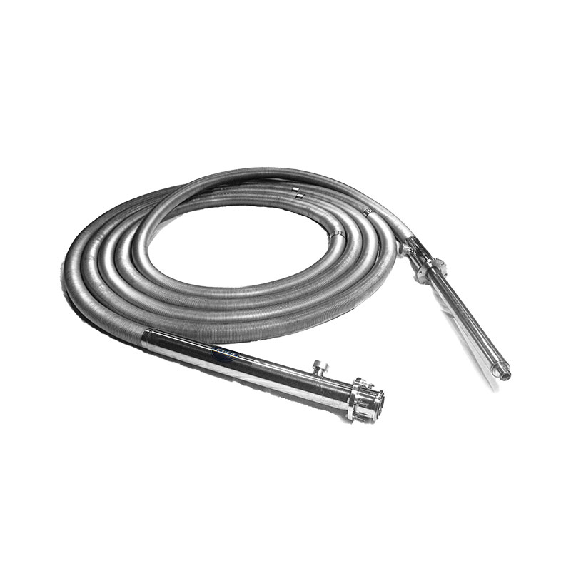
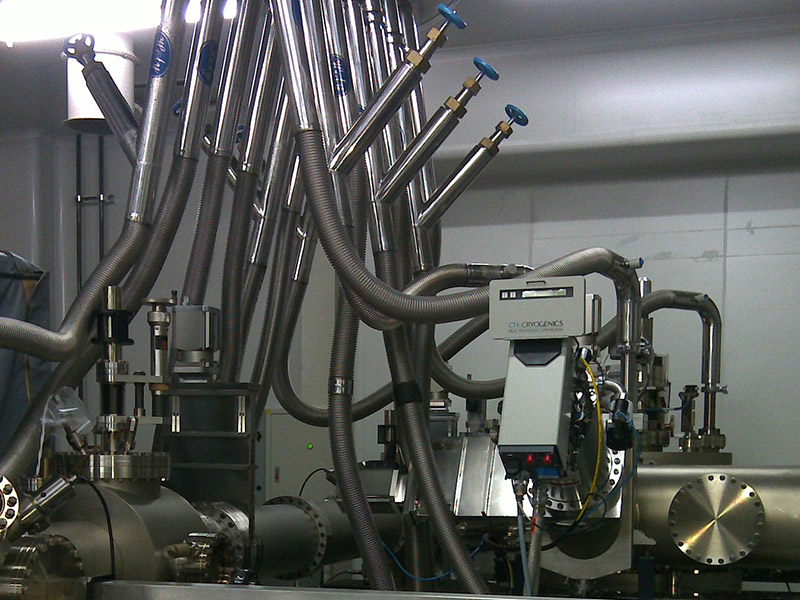
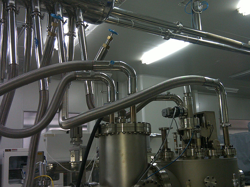
Vacuum Insulated Flexible Hose Series
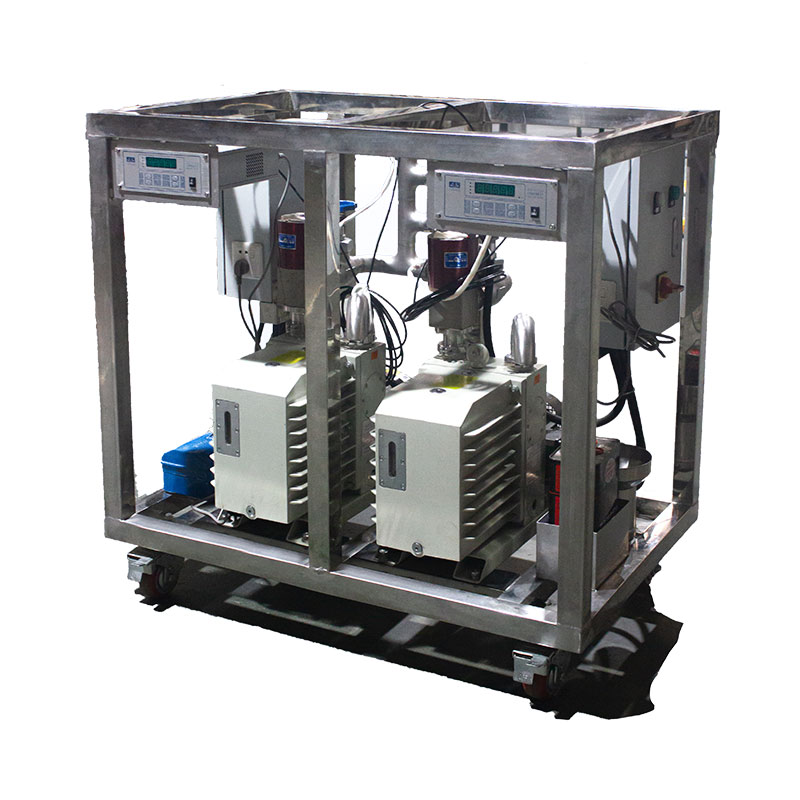
Dynamic Vacuum Pump System
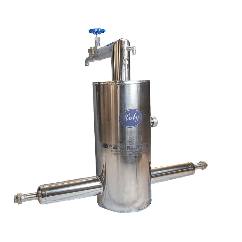
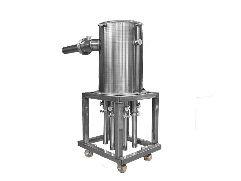
Vacuum Insulated Phase Separator Series
Vacuum Insulated Valve Series
Piping System Support Equipment
MOLECULAR BEAM EPITAXY
The technology of Molecular Beam Epitaxy (MBE) was developed in the 1950s to prepare semiconductor thin film materials using vacuum evaporation technology. With the development of ultra-high vacuum technology, the application of technology has been extended to the field of semiconductor science.
HL has noticed the demand of MBE liquid nitrogen cooling system, organized technical backbone to successfully develop a special MBE liquid nitrogen cooing system for MBE technology and a complete set of vacuum insulated piping system, which has been used in many enterprises, universities and research institutes.
The common problems of the semiconductor & chip industry include,
- The Pressure of Liquid Nitrogen into Terminal (MBE) Equipment. Prevent Pressure Overload from Damaging Terminal (MBE) Equipment.
- Multiple Cryogenic Liquid Inlet and Outlet Controls
- The Temperature of Liquid Nitrogen into Terminal Equipment
- A Reasonable Amount of Cryogenic Gas Emissions
- (Automatic) Switching of Main and Branch Lines
- Pressure Adjustment (Reducing) and Stability of VIP
- Cleaning Away the Possible Impurities and Ice Residue from Tank
- Filling Time of the Terminal Liquid Equipment
- Pipeline Precooling
- Liquid Resistance in VIP System
- Control Loss of Liquid Nitrogen During Discontinuous Service of the System
HL's Vacuum Insulated Pipe (VIP) is built to ASME B31.3 Pressure Piping code as a standard. Engineering experience and quality control ability to ensure the efficiency and cost-effectiveness of the customer's plant.
SOLUTIONS
HL Cryogenic Equipment provides customers with the Vacuum Insulated Piping System to meet the requirements and conditions of the semiconductor & chip industry:
1.Quality Management System: ASME B31.3 Pressure Piping Code.
2.A Special Phase Separator with Multiple Cryogenic Liquid Inlet and Outlet with automatic control function meets the requirement of gas emission, recycled liquid nitrogen and temperature of liquid nitrogen.
3.Adequate and timely exhaust design ensures that terminal equipment always works within the designed pressure value.
4.The Gas-liquid Barrier is placed in the vertical VI pipe at the end of VI pipeline. Gas-liquid Barrier uses the gas seal principle to block the heat from the end of the VI pipeline into the VI Piping, and effectively reduce the loss of liquid nitrogen during discontinuous and intermittent service of the system.
5.VI Piping Controlled by The Vacuum Insulated Valve (VIV) : Including Vacuum Insulated (Pneumatic) Shut-off Valve, Vacuum Insulated Check Valve, Vacuum Insulated Regulating Valve etc. Various types of VIV can be modular combined to control the VIP as required. VIV is integrated with VIP prefabrication in manufacturer, without on-site Insulated treatment. The seal unit of VIV can be replaced easily. (HL accepts the cryogenic valve brand designated by customers, and then makes vacuum insulated valves by HL. Some brands and models of valves may not be able to be made into vacuum insulated valves.)
6.Cleanliness, if there are additional requirements for inner tube surface cleanliness. It is suggested that customers choose BA or EP stainless steel pipes as VIP inner pipes to further reduce stainless steel spillage.
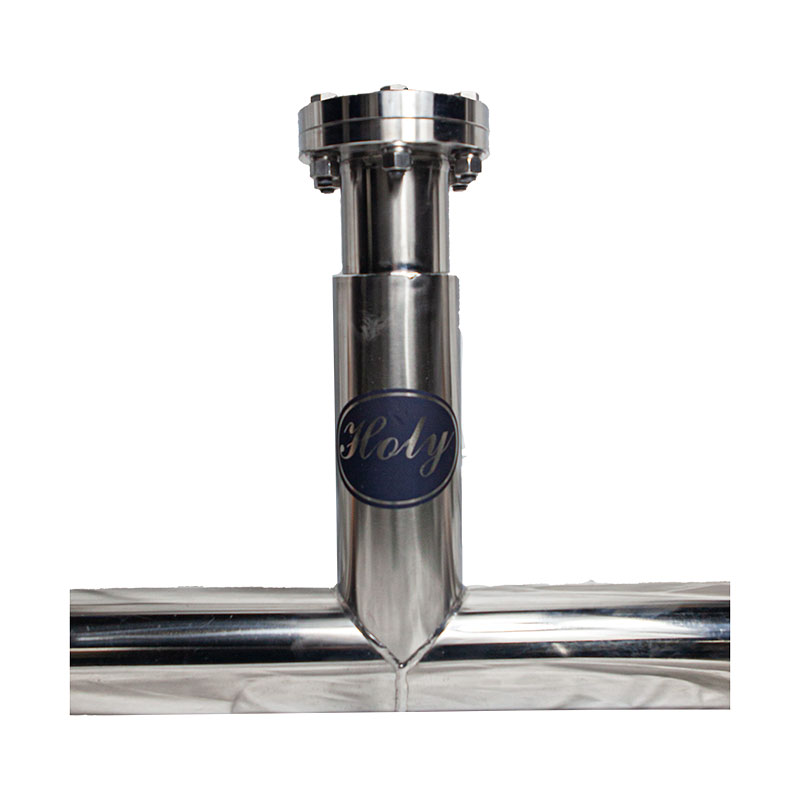
7.Vacuum Insulated Filter: Clean away the possible impurities and ice residue from tank.
8.After a few days or longer shutdown or maintenance, it is very necessary to precool the VI Piping and terminal equipment before cryogenic liquid is entered, so as to avoid ice slag after cryogenic liquid directly enters the VI Piping and terminal equipment. Precooling function should be considered in design. It provides better protection for terminal equipment and VI Piping support equipment such as valves.
9.Suit for both Dynamic and Static Vacuum Insulated (Flexible) Piping System.
10.Dynamic Vacuum Insulated (Flexible) Piping System: Consist of VI Flexible Hoses and/or VI Pipe, Jumper Hoses, Vacuum Insulated Valve System, Phase Separators and Dynamic Vacuum Pump System (including the vacuum pumps, solenoid valves and vacuum gauges etc.). The length of single VI Flexible Hose can be customized according to user’s requirements.
11.Various Connection Types: Vacuum Bayonet Connection (VBC) Type and Welded Connection can be selected. The VBC type do not need on-site insulated treatment.


