
In semiconductor manufacturing, cryogenic distribution systems are expected to do more than simply transfer liquid nitrogen or argon from one point to another. The fluid has to remain stable, clean, and single-phase all the way to the point of use. Even small amounts of heat ingress can generate flash gas, pressure fluctuation, or moisture contamination that affects process stability.
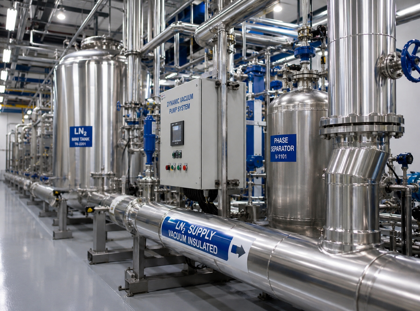
That is why Vacuum Insulated Pipe systems are commonly used in semiconductor fabs instead of conventional foam-insulated piping. When combined with a properly managed Dynamic Vacuum Pump System, the overall heat leak can remain below 3 W/m while maintaining long-term vacuum stability across the entire transfer line.
For semiconductor applications, vacuum insulation should not be viewed as a passive layer around the pipe. It is an active thermal system that requires measurable vacuum performance and long-term maintainability. In high-precision chip manufacturing environments, even a slight increase in fluid saturation temperature may lead to two-phase flow conditions that interfere with cooling circuits, purification systems, or process control equipment.
Why Heat Leak Matters in Cryogenic Semiconductor Systems
Every cryogenic transfer line is affected by three primary forms of heat transfer:
- radiation across the annular space
- gaseous conduction caused by residual molecules
- solid conduction through supports and spacers
In a properly designed Vacuum Insulated Pipe, the annular pressure is typically reduced below 1×10⁻⁴ Pa. At that vacuum level, the remaining gas molecules have a mean free path significantly larger than the annular gap, which greatly reduces gaseous heat conduction.
Radiative heat transfer is controlled using multi-layer insulation (MLI). The insulation consists of alternating layers of reflective foil and low-conductivity spacer material. With the correct layer density and installation method, radiative heat flux can be reduced to only a few watts per square metre.
The remaining thermal path comes mainly from mechanical supports. To minimize this effect, low-conductivity materials such as G-10 fiberglass or Torlon® are typically used. These supports still need enough mechanical strength to tolerate thermal contraction, vibration, and seismic loading during operation.
Over long transfer distances, the difference between vacuum insulation and foam insulation becomes very noticeable. A well-maintained vacuum system can maintain stable thermal performance for many years, while foam insulation gradually absorbs moisture from the atmosphere. Once moisture enters the insulation structure and freezes, thermal efficiency usually declines over time.
In practical semiconductor LN₂ distribution systems, vacuum-insulated piping can reduce boil-off significantly compared with traditional foam-insulated lines, especially on long outdoor runs or continuously operating main headers.
Dynamic Vacuum Pump System
One issue with static vacuum jackets is that vacuum quality may slowly deteriorate over the years due to outgassing, helium permeation, or microscopic leakage.
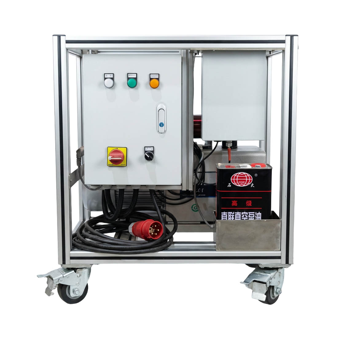
To address this, large-diameter Vacuum Insulated Pipe systems can be equipped with a Dynamic Vacuum Pump System. The system normally includes a compact turbomolecular or scroll pump arrangement that periodically restores the annular vacuum to its original design condition.
Vacuum levels are monitored continuously using cold-cathode gauges. The pump only activates when pressure rises beyond the target setpoint, so power consumption and maintenance requirements remain relatively low.
In one semiconductor facility upgrade project in Hsinchu, Taiwan, an actively managed vacuum pumping system allowed an aging LN₂ transfer header to recover thermal performance close to its original operating condition without shutting down the production line. For new projects, active vacuum maintenance also gives operators better confidence in long-term insulation stability throughout the service life of the system.
Materials and System Design
For semiconductor and ultra-high-purity applications, the inner process pipe is typically manufactured from 304L or 316L stainless steel. Internal surfaces are cleaned, purged, and passivated to meet oxygen-clean service requirements and minimize contamination risk.
The outer jacket may use painted carbon steel or stainless steel depending on the installation environment. In cleanroom-adjacent areas, stainless outer jackets are often preferred to avoid corrosion or surface contamination.
Thermal contraction also needs to be considered carefully. An LN₂ transfer line can contract approximately 2.5–3 mm per metre between ambient temperature and operating temperature. To absorb this movement, bellows-type expansion compensators are usually installed at calculated anchor locations throughout the piping network.
Where movement or flexibility is required, Vacuum Insulated Flexible Hose assemblies are commonly used. Typical locations include tank connections, equipment hook-ups, manifold branches, and mobile process skids.
These flexible hoses use a corrugated inner core together with a vacuum jacket and MLI structure similar to rigid vacuum pipe. Properly designed assemblies can maintain vacuum integrity after repeated cryogenic thermal cycling while also preventing external ice formation that is common on non-insulated braided hoses.
Vacuum Insulated Valves and Phase Separators
Managing heat leak is not limited to straight pipe sections. Valves and phase separators also play a major role in maintaining stable cryogenic flow conditions.
A Vacuum Insulated Valve normally uses an extended bonnet and vacuum-jacketed body to keep critical sealing areas away from extremely low temperatures. This helps prevent freezing around stem packing and reduces unwanted condensation inside the valve structure.
Without vacuum insulation, valves can become concentrated heat-leak points within the system. In liquid cryogenic service, this may generate localized vapor pockets, unstable flow conditions, or water hammer events.
For semiconductor process systems, extended-bonnet globe valves and top-entry ball valves are commonly used in accordance with ASME B31.3 and EN 13480 requirements.
A Vacuum Insulated Phase Separator is used to remove flash gas before liquid enters sensitive downstream equipment. In semiconductor applications, unstable two-phase flow can create pressure swings large enough to trigger process alarms or equipment interlocks.
Most separator designs use a tangential inlet together with an internal demister structure to improve vapor-liquid separation efficiency. In many projects, the separator is combined with a Mini Tank installed near the process floor. The mini tank acts as a local buffer volume that helps stabilize short-term demand fluctuations without introducing significant additional heat load.
Semiconductor Project Example
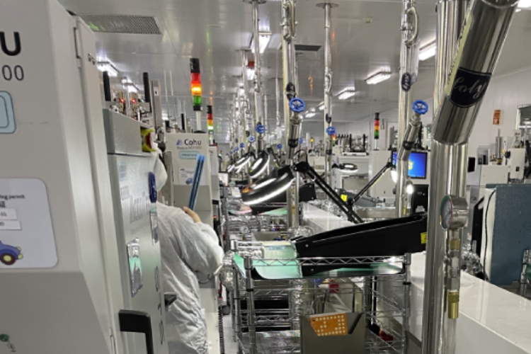
A DRAM facility expansion project in South Korea required a new LN₂ distribution network serving immersion-cooled test equipment and wafer processing tools.
The installation included approximately 180 metres of rigid Vacuum Insulated Pipe connected to multiple tool branches through Vacuum Insulated Flexible Hose assemblies. A Vacuum Insulated Phase Separator and a 2 m³ Mini Tank were installed near the bulk storage area.
The Dynamic Vacuum Pump System maintained annular pressure below 5×10⁻⁶ mbar on the main 6-inch transfer lines.
During commissioning, measured heat leak on the primary header averaged approximately 1.3 W/m under stable operating conditions. After one year of continuous service, periodic vacuum recovery cycles kept the insulation performance close to the original baseline condition.
Compared with the previous foam-insulated concept, the facility reported noticeably lower liquid nitrogen losses and improved operating stability. Process logs also showed no moisture-related contamination events associated with insulation degradation.
Applications
Vacuum-insulated cryogenic transfer systems are widely used in semiconductor manufacturing, LNG infrastructure, industrial gas distribution, and liquid hydrogen applications.
Although the operating environments differ, the engineering objective remains the same:
- maintain vacuum stability
- minimize heat ingress
- preserve phase stability throughout the transfer process
System design normally follows international standards such as ASME B31.3, EN 13480, and ISO 21029 depending on project scope and regional requirements.
For semiconductor facilities, the performance of the cryogenic distribution system directly affects operating efficiency, liquid consumption, and long-term process reliability. Because of that, piping, valves, separators, and vacuum maintenance systems should be designed as one integrated thermal system rather than independent components.
At HL Cryogenics, we work with EPC contractors, gas companies, and semiconductor facilities to develop cryogenic transfer solutions based on actual operating conditions, thermal load targets, and installation requirements rather than standard catalogue configurations.
If you are planning a new semiconductor fab project or upgrading an existing LN₂ distribution network, our engineering team can help evaluate heat leak performance, vacuum strategy, and system configuration for long-term operation.
Post time: May-18-2026


